Technical Tuning Reference
Calibration theory, graph interpretation, and FYIs.
Automated Map Discovery & Variant Handling
When loading a binary file that lacks a pre-established map definition profile, the backend sniffer automatically executes to locate, identify, and describe missing maps.
This ensures that custom or rare software versions can still be parsed.
Understanding Codeblock Variants
Factory engine management systems frequently store multiple duplicate blocks of core maps. In almost all cases, separate codeblocks are designated for different transmission configurations (e.g., manual vs. automatic gearboxes).
When tuning, ensure you are modifying the active codeblock corresponding to your vehicle's hardware setup to actually achieve the desired performance improvements.
Reading the Core Graphs & Data Stories
Moving past basic slider manipulation, the visualizer charts tell a complete story of engine behavior:
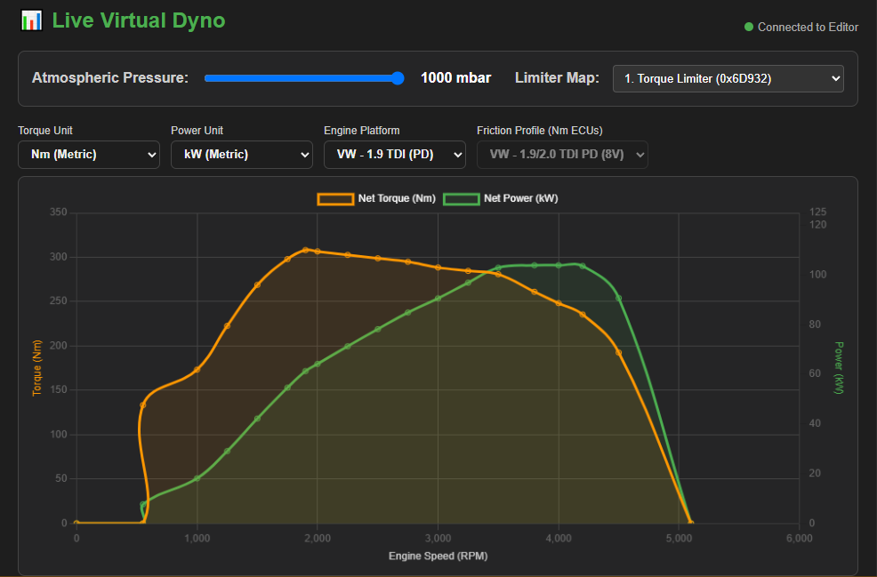
- Dyno Estimates: Monitor real-time calculated torque and power figures as modifications are applied to the torque limiter map.
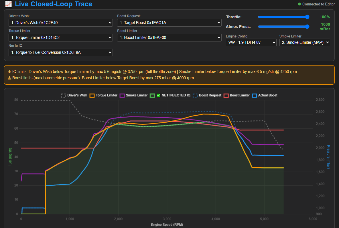
- Limiter Traces: Monitor real-time limits that could be hindering your engine's performance and apply changes as you go.
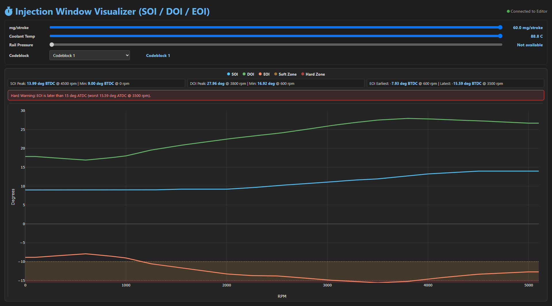
- Fuel Injection: Track shifts in Start of Injection (SOI), End of Injection (EOI), and Duration of Injection (DOI) as the engine transitions through the coolant temperature-based selection map.
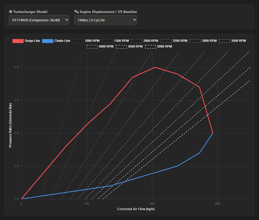
- Compressor Map: Visualizes the turbocharger compressor's operating points, helping to tune target boost and boost limit for your setup.
Using the Web Tool
-
Starting a Project: Go into the "Projects" section to set up your first project.
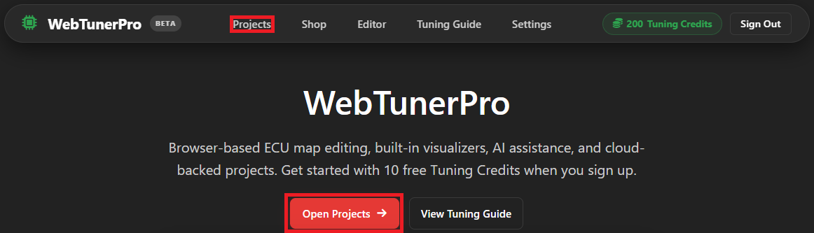 Once you're in the "Projects" section, click "Upload .BIN".
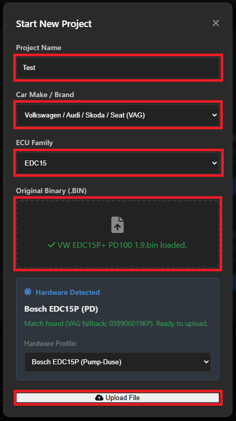
 Fill in the name of the project, select which brand the ECU belongs to, select which ECU family it belongs to and select the file you want to work on and click "Upload File".
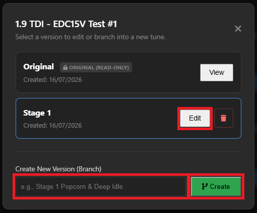
 Once the file is uploaded, start by creating a version of the project to begin tuning. Fill in the name and click "Create", once the new version exists just click on "Edit"
-
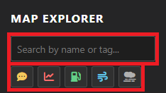
Editing a Project: Once you have the project loaded into the editor, you can make changes to the maps as needed. There is a search bar and category sorting buttons to help you find the maps you need.
 The maps in the map list are color-coded to indicate their status.
Gray means they are verified manually (safe to assume they are correct).
Green means they were found automatically and it looks like it's a good match (on rare occasions may be a false positive).
Orange means that they were found automatically but the map sniffer is not completely confident this map is a match (usually the lack of confidence stems from floating axes or map being flat).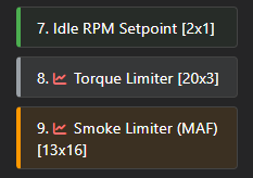 There are also various charts to assist you in tuning and monitoring/troubleshooting the performance of your project.
  Virtual Dyno: Shows you an estimated torque curve, assisting you in shaping the torque limiter map.
  Limiter Trace: King of troubleshooting, shows you how the driver's wish, smoke limiter and torque limiter maps interact with one-another along with boost maps. If one is limiting another, there is a warning to let you know about it.
 Injection Window: Plots the Start of Injection, Duration of Injection and End of Injection so you can visually see injector behavior. If your end of injection approaches dangerous levels there is a soft warning and a hard warning to help guide you.
 Compressor Map: Visualizes the compressor map of your chosen turbocharger, helping you tune your boost limiter and target boost maps. You can also use these graphs to estimate maximum power potential (for a diesel engine you can assume absolute maximum power as HP = kg/h x 0.36 - if running a smokey tune).
-
Map Editing: Map editors are loaded with features that help you in tuning your maps efficienctly. There is a history to each map so you can undo/redo changes, you can switch between table view and graph view, and if you prefer looking at your map flipped you can click on "Switch Axes".
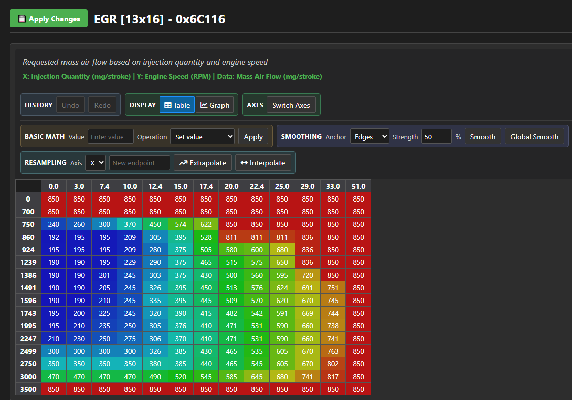 Basic Math: Allows you to perform basic arithmetic operations directly within the map editor, making it easier to adjust multiple cells at a time. "Set Value" directly sets the selected cells to a specified value, "Add" adds and "Subtract" subtracts the specified value to/from the selected cells, "Multiply" multiplies and "Divide" divides the selected cells by the specified value and "Add percentage" adds a percentage value to the selected cells.
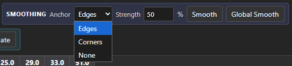
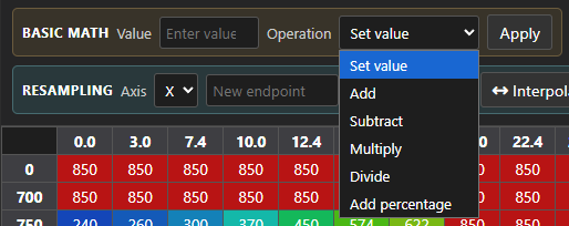 Smoothing: Allows you to smooth out the values in the map to create a more gradual transition between cells, helping to avoid abrupt changes that could negatively impact engine performance.
"Edges" option anchors the edges of your selection to prevent them from being smoothed, "Corners" option anchors the corners of your selection and "None" disables any anchoring, allowing extrapolation to be performed to attempt to fit the corners/edges of the selection into our rough trend.
Strength allows you to control the intensity of the smoothing effect applied to the selected cells.
"Smooth" acts as a local averaging function, applying the smoothing effect primarily to the selected cells while considering the surrounding cells to create a more gradual transition. "Global Smooth" draws an invisible target in the form of a flat sheet that takes into consideration your anchor points.
Simply select the cells you want to smooth and apply the desired smoothing options.
Smoothing: Allows you to smooth out the values in the map to create a more gradual transition between cells, helping to avoid abrupt changes that could negatively impact engine performance.
"Edges" option anchors the edges of your selection to prevent them from being smoothed, "Corners" option anchors the corners of your selection and "None" disables any anchoring, allowing extrapolation to be performed to attempt to fit the corners/edges of the selection into our rough trend.
Strength allows you to control the intensity of the smoothing effect applied to the selected cells.
"Smooth" acts as a local averaging function, applying the smoothing effect primarily to the selected cells while considering the surrounding cells to create a more gradual transition. "Global Smooth" draws an invisible target in the form of a flat sheet that takes into consideration your anchor points.
Simply select the cells you want to smooth and apply the desired smoothing options.
 Original Map:
 Smooth:
 Global Smooth:
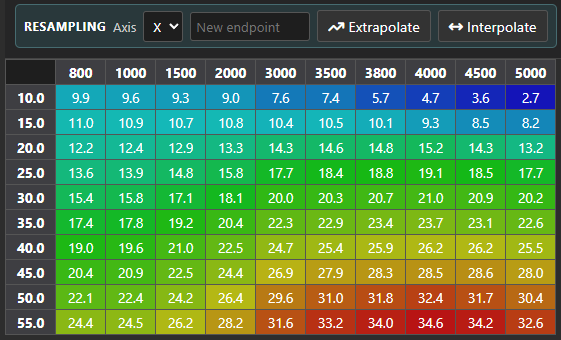
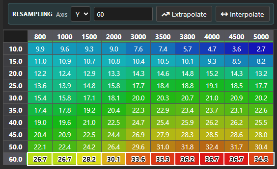
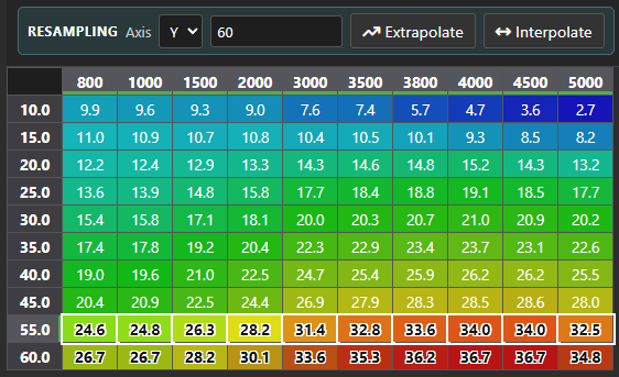
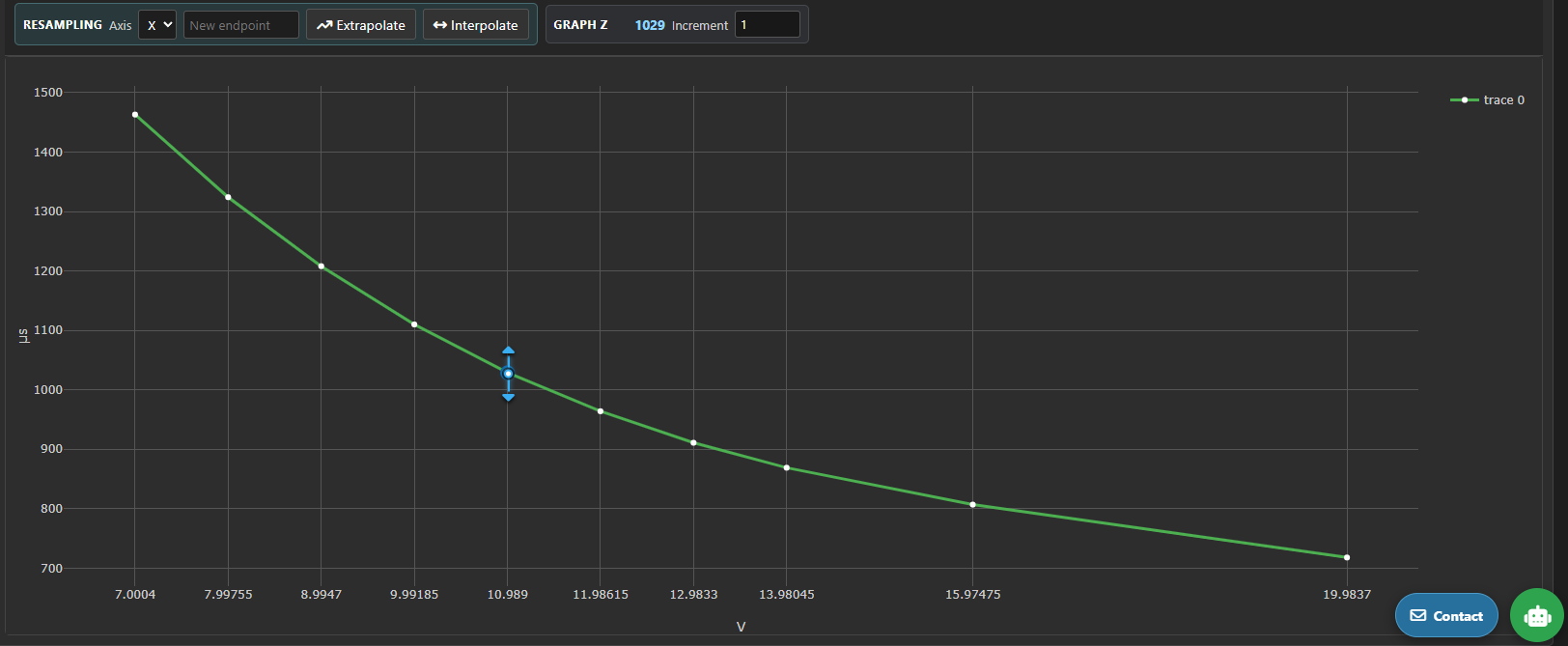
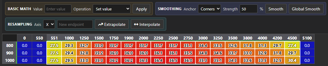 Resampling: Allows you to extrapolate the map i.e. when calibrating injectors for higher fuel flow and also allows you to interpolate, useful if moving axes around or copying calibration data from another ECU for retrofitted hardware and you have more resolution available.
To extrapolate, select the axis in the dropwdown menu and specify what you want the new highest value you want on that axis to be and click "Extrapolate". To interpolate, change the axis header cell to the desired new value, select the cells you want to interpolate (must be only 1 row or 1 column!) and click "Interpolate".
Resampling: Allows you to extrapolate the map i.e. when calibrating injectors for higher fuel flow and also allows you to interpolate, useful if moving axes around or copying calibration data from another ECU for retrofitted hardware and you have more resolution available.
To extrapolate, select the axis in the dropwdown menu and specify what you want the new highest value you want on that axis to be and click "Extrapolate". To interpolate, change the axis header cell to the desired new value, select the cells you want to interpolate (must be only 1 row or 1 column!) and click "Interpolate".
 Original Map:
 Extrapolation:
 Interpolated Map:
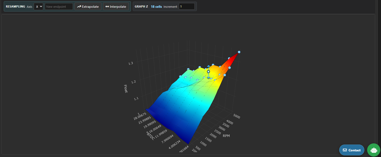
 The editor also supports 3D editing for those who are more visual tuners. Simply set the increment to your liking i.e. if you want 25 mBar incremental changes as you move the arrows up and down for example, then select the cell(s) you want to move around and drag the arrows.
-
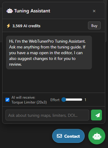
AI Assistant: There is an AI assistant to help you in time of need if you lack experience and knowledge and/or time.
The AI has access to your list of map names and current map data (ensuring your have ticked the checkbox on the lower left side of the chat).
It is being slowly trained on various tuning examples and is fed various injector and turbocharger calibration data from time to time along with official documentation of various technologies.
Map-Specific Guidelines
- Boost Limiter: Sets the boost limit for the given turbocharger and engine combination based on barometric pressure and engine speed. When unsure, leave the low engine speed and barometric pressure zones stock or close to stock values. Biggest adjustments are to be made in the midrange of the engine speed zone and highest barometric pressure zone - when unsure, use the Compressor Map visualizer for assistance.
- Driver's Wish: Sets the desired injection quantity or torque based on throttle input and engine speed. Highly advised to leave the low engine speed and low throttle input zones stock or close to stock values. Biggest adjustments are to be made at the highest throttle input zones - keep an eye on the Limiter Trace chart to make sure it is always higher than the Torque Limiter.
- Duration of Injection: Sets the required injection duration in crankshaft degrees or microseconds for given injection quantity and engine speed. Leave all the stock data as is and just extrapolate using linear extrapolation - unless your goal is some form of complex anti-lag or potentially lope-idle.
- EGR Target Airflow: Sets the reqested airflow for the engine based on injection quantity and engine speed. Used mostly for emissions purposes, but also sometimes for noise suppression and potentially throttle feel. If you want to disable it then set all the values to the maximum value found in the map, or set the EGR Hysteresis maps to 0 across the operating range.
- Inverse Driver's Wish: Tells the ECU what throttle percentage is needed to achieve a certain amount of injection quantity or torque based on injection quantity and engine speed, typically used by the ECU for cruise control. Use basic linear interpolation on the Driver's Wish map to set this map correctly.
- N75 Duty Cycle: Sets the required duty cycle for the N75 solenoid controlling the turbocharger wastegate/variable geometry based on injection quantity and engine speed. Proper calibration ensures optimal boost response and prevents overboost conditions, log your car properly to see the baseline performance, especially if a turbocharger upgrade was performed. Basic first step is to extrpolate known factory values whilst leaving factory values present. Log the car again and adjust as required.
- Smoke Limiter (MAF): Sets the maximum allowable injection quantity based on mass airflow (MAF) and engine speed. Proper calibration helps maintain emissions compliance and prevents excessive smoke. Start with factory values and adjust gradually while monitoring exhaust smoke levels, throttle feel and limitations found while logging. As a starting step, estimate the mass flow based on your Target Boost map and populate the map accordingly, good rule of thumb is to leave at least 1% margin above the torque limiter. When unsure, check the Limiter Trace chart.
- Smoke Limiter (MAP): Sets the maximum allowable injection quantity based on manifold absolute pressure (MAP) and engine speed. Proper calibration helps maintain emissions compliance and prevents excessive smoke. Start with factory values and adjust gradually while monitoring exhaust smoke levels, throttle feel and limitations found while logging. As a starting step, look at your Target Boost map to see roughly which zones need to be bumped up, good rule of thumb is to leave at least 1% margin above the torque limiter. When unsure, check the Limiter Trace chart.
- Start of Injection: Sets the desired start of injection in crankshaft degrees for given injection quantity and engine speed. Start with factory values and adjust gradually while monitoring engine response and emissions. Good rule of thumb is to keep the end of injection (EOI) no later than 10 degrees after top dead center (ATDC) unless you are creating an anti-lag strategy or want aggressive pops. If unsure, check the Injection Visualizer chart.
- Target Boost: Sets the desired boost pressure for the turbocharger based on injection quantity and engine speed. Start with factory values and adjust gradually while monitoring boost levels, ensuring no aggressive overboost, exhaust manifold pressure (EMP) and engine response. Good rule of thumb is to leave the lower and higher engine speed zones stock or close to stock and copy over the highest injection quanity zone over to the new highest injection quantity set in the Torque Limiter map and estimate roughly 17:1-17.5:1 air fuel ratio (AFR) to avoid smoke..
- Torque Limiter: Sets the maximum allowable injection quantity or torque output based on engine speed and sometimes barometric pressure. Good rule of thumb is to not touch low or higher engine speed (and barometric pressure, if it's a 3D map) zones, for the midrange a nice progressive torque increase is suggested to avoid any weird sudden acceleration spikes and wheelspin. If your clutch is worn and/or your turbocharger is not in the best condition it would be advisable to keep the lower engine speeds even closer to stock.
VP Architecture & Calibration Overview
Older Verteilerpumpe (VP) systems (such as EDC15V found on early TDI powerplants) rely on mechanical-electronic control of fuel quantity via a sliding collar or metering unit.
These are usually hassle-free to work on, but require close attention to start of injection as there are no direct duration of injection maps for you to be able to calculate end of injection accurately.
PD Architecture & Calibration Overview
Pumpe-Düse (PD) systems, also known as unit injector systems, integrate the injector and high-pressure pump into a single unit for each cylinder.
These are more complex than VP-based ECUs requiring more attention to detail, but offer finer control over injection timing and quantity for each cylinder allowing you to more easily implement lope idle, anti-lag, popcorn limiters, etc.
Common Rail Architecture Overview
Common Rail (CR) systems utilize a high-pressure fuel rail to supply fuel to solenoid or piezo injectors, allowing for precise control over injection timing, duration, and quantity independent of engine speed and load.
These systems are generally easier to tune than PD systems due to injection duration being directly linked to rail pressure and engine speed removing the need for having 6-7 duration of injection maps, but still require careful attention to rail pressure, injection timing, and multi-injection strategies to achieve optimal performance and emissions compliance.
FYI: PID Controller Behavior on Boost
The factory ECU utilizes a Proportional-Integral-Derivative (PID) control loop to reconcile actual boost pressure against requested target boost via the N75 valve.
When target maps are altered too aggressively without tuning the proportional and integral gain maps, the PID error correction loop can induce chronic pressure oscillation, manifesting as boost surge or severe spiking.
FYI: Atmospheric Compensation via N75 & Weighting Curves
Factory calibrations scale boost targets and N75 duty cycles dynamically against changing barometric pressures. Weighting maps dictate which target boost and N75 duty cycle maps to use (if multiple are present), ensuring consistent turbocharger performance across high-altitude and sea-level driving conditions.
FYI: The Critical Importance of BIP Maps
Beginning of Injection Period (BIP) maps track electronic feedback from Pumpe-Düse unit injectors to measure internal solenoid response times and mechanical wear.
Ignoring or failing to calibrate BIP correction values when scaling high-flow injectors can lead to severe timing discrepancies, erratic idle control, and cylinder-to-cylinder fueling imbalances.